Architecting Real-Time Hydraulic Fidelity: A Technical Deep Dive into SCADA-Driven Model Calibration Loops
Architecting Real-Time Hydraulic Fidelity: A Technical Deep Dive into SCADA-Driven Model Calibration Loops
Optimize grid resilience by bridging the gap between SCADA telemetry and Hydraulic Modeling through automated real-time calibration loops.
- Architecting Real-Time Hydraulic Fidelity: A Technical Deep Dive into SCADA-Driven Model Calibration Loops
- The Architecture of the Feedback Loop
- Performance Metrics: Static vs. Real-Time Calibration
- Hidden Technical Pitfalls
- Implementation: Data Reconciliation via SQL
- Adhering to Engineering Standards
- Conclusion
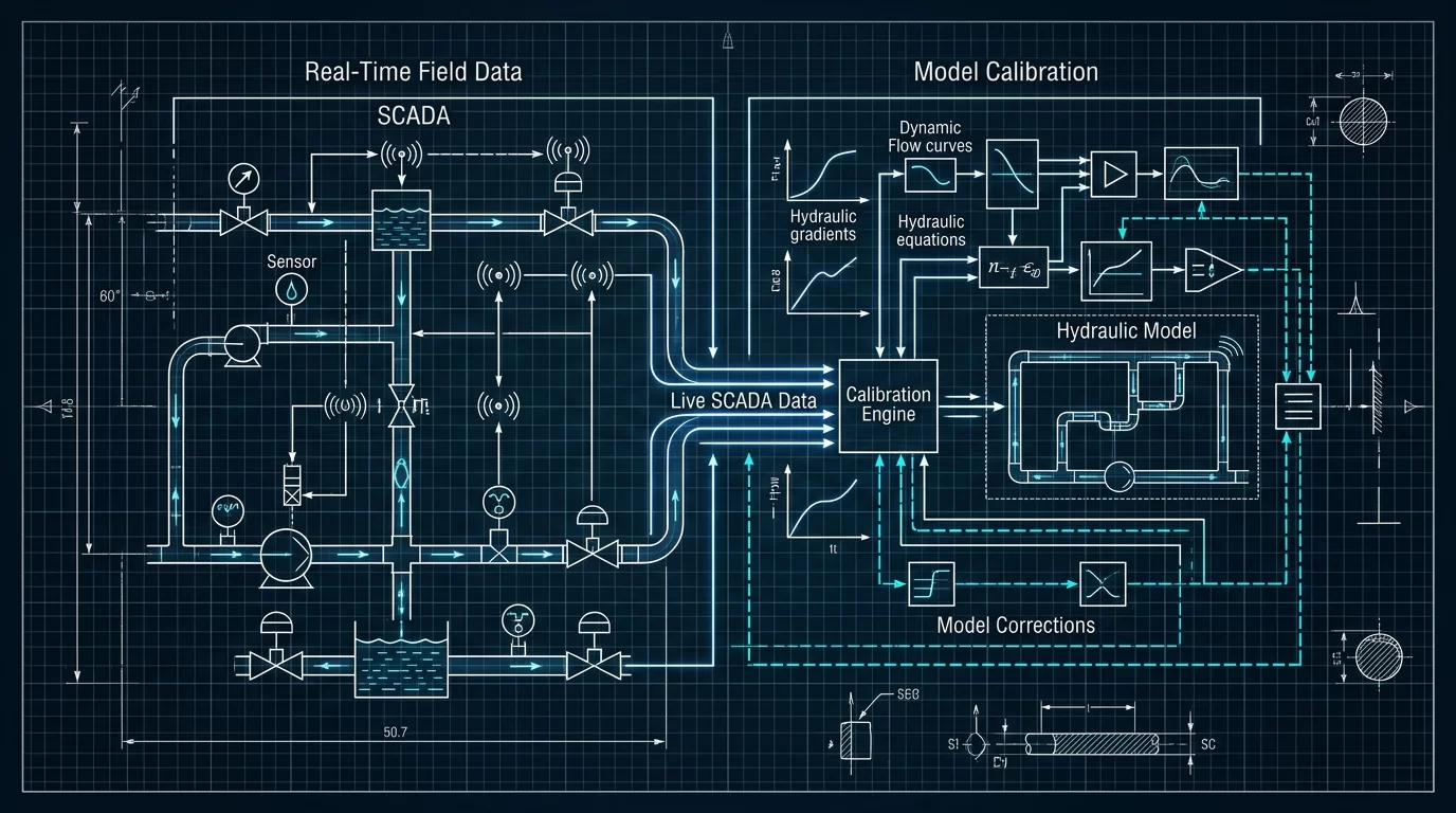
For decades, Hydraulic Modeling and SCADA operations lived in silos. The model was a design tool; the SCADA system was an operational tool. However, as energy grids and water distribution networks face increasing volatility, the need for a Digital Twin that reflects current physical reality has become paramount. Field Automation Engineers are now tasked with architecting calibration loops that ingest high-frequency SCADA data to update hydraulic parameters (such as pipe roughness or nodal demand) in near real-time. This technical deep dive explores the architecture of these loops, the hidden pitfalls of data synchronization, and the performance metrics that define success.
The Architecture of the Feedback Loop
A robust calibration loop is not merely a data transfer script; it is a multi-layered architecture designed for high availability and data integrity. At the edge, PLCs and RTUs collect pressure, flow, and tank level data. This data is ingested by the SCADA historian. The calibration engine—often a specialized middleware—queries the historian, cleans the data, and executes an optimization algorithm (typically Genetic Algorithms or Levenberg-Marquardt) to minimize the delta between observed SCADA values and predicted model values.
To ensure security and reliability, these architectures must adhere to IEC 62443 standards for industrial communication. By implementing “zones and conduits,” engineers can ensure that the data flow from the operational technology (OT) environment to the modeling environment (often residing in a DMZ or cloud) does not introduce vulnerabilities into the critical infrastructure.
Performance Metrics: Static vs. Real-Time Calibration
The following table illustrates the performance shift when moving from traditional snapshot-based calibration to a SCADA-driven automated loop.
| Metric | Static Snapshot (Manual) | SCADA-Driven (Real-Time) | Operational Impact |
|---|---|---|---|
| Calibration Frequency | Quarterly / Annually | 5 – 15 Minutes | Detects transient anomalies immediately. |
| Mean Absolute Error (MAE) | 8% – 15% | < 3% | Higher confidence in automated setpoint control. |
| Boundary Condition Fidelity | Assumed / Averaged | Live Telemetry | Accurate surge and pressure zone modeling. |
| Regulatory Compliance | Post-event Reporting | Proactive Compliance | Meets EPA and AWWA quality standards. |
Hidden Technical Pitfalls
Despite the benefits, several technical hurdles can undermine the fidelity of a real-time hydraulic model:
- Time-Stamp Aliasing: SCADA systems often use report-by-exception (RBE) protocols. If the hydraulic engine expects data at a fixed 1-minute interval but the SCADA historian only records changes, the model may ingest “stale” data, leading to divergence.
- Sensor Drift and Noise: A single malfunctioning pressure transducer can force the calibration algorithm to adjust pipe roughness to impossible levels to compensate for the bad data. Implementing a pre-processing layer for outlier detection is critical.
- Computational Latency: In large-scale grids with 50,000+ nodes, running a full hydraulic simulation and optimization loop within a 5-minute SCADA scan cycle requires significant compute resources and efficient matrix solvers.
Implementation: Data Reconciliation via SQL
To bridge the gap between RBE SCADA data and the fixed-step requirements of hydraulic solvers, engineers often use time-weighted averaging. Below is a SQL example used in a historian interface to prepare data for a calibration engine, ensuring we capture the most representative value for a specific time window.
-- Aggregating SCADA Telemetry for Hydraulic Model Input
-- Uses time-weighted average to handle Report-By-Exception data
SELECT
    TAG_NAME,
    DATEADD(minute, DATEDIFF(minute, 0, TIMESTAMP) / 15 * 15, 0) AS IntervalStart,
    SUM(VAL * CAST(DATEDIFF(second, LAG_TIME, TIMESTAMP) AS FLOAT)) /
    SUM(DATEDIFF(second, LAG_TIME, TIMESTAMP)) AS TimeWeightedAvg
FROM (
    SELECT
        TAG_NAME,
        TIMESTAMP,
        VALUE AS VAL,
        LAG(TIMESTAMP) OVER (PARTITION BY TAG_NAME ORDER BY TIMESTAMP) AS LAG_TIME
    FROM SCADA_HISTORIAN_RAW
    WHERE TIMESTAMP >= GETDATE() - 1
) AS SubQuery
GROUP BY TAG_NAME, DATEADD(minute, DATEDIFF(minute, 0, TIMESTAMP) / 15 * 15, 0);
Adhering to Engineering Standards
In North America, the AWWA M32 manual provides the framework for hydraulic network modeling, but it was written primarily for static analysis. Modern architects must augment these guidelines with NERC CIP requirements if the hydraulic model is used to automate decisions in energy-intensive pump stations or hydro-generation facilities. Ensuring that the calibration loop does not become a vector for “man-in-the-middle” attacks is a requirement for modern grid architecture.
Furthermore, referencing research from the IEEE Xplore Digital Library regarding state estimation in power systems provides a blueprint for similar applications in hydraulic fidelity. The American water Works Association (AWWA) continues to update its standards to reflect the move toward smart water grids and real-time modeling.
Conclusion
Architecting a SCADA-driven calibration loop is an exercise in balancing physical reality with digital precision. By moving away from static snapshots and toward continuous fidelity, Energy Grid Architects can transform their hydraulic models from passive reference tools into active, predictive assets. The key to success lies in rigorous data cleansing, adherence to cybersecurity standards like NIS2 or IEC 62443, and the implementation of robust mathematical solvers that can keep pace with the heartbeat of the grid.